

Raspberry Pi as a SCSI device
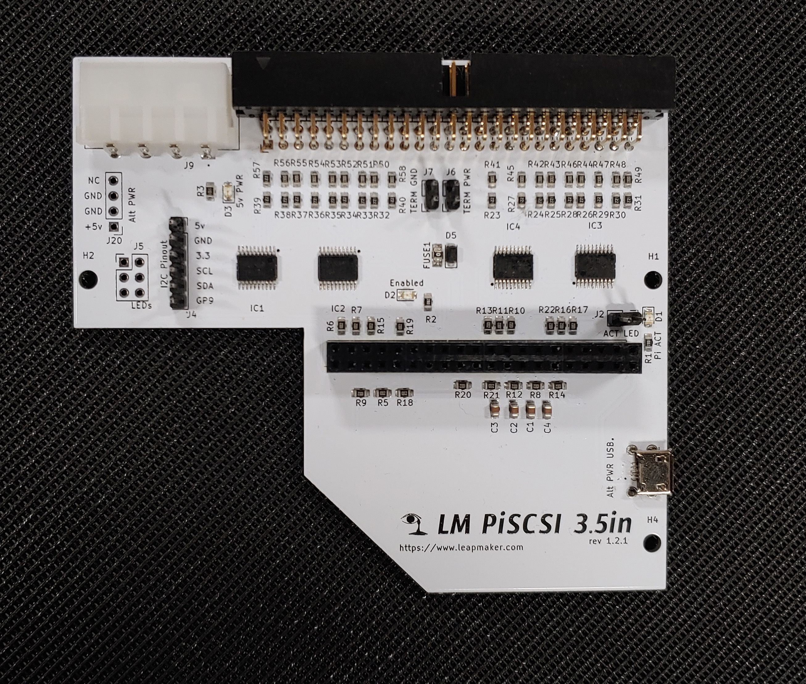
- 3.5in PiSCSI fullspec board.
- Designed to be used in a 3.5in half hight HDD space
- I2C connector for LED display
- Standard 50-pin SCSI interface
- Multiple power connector options (5v input)
Suggested read about SCSI: How stuff works on SCSI
Apply the jumpers at J6 and J7 to enable onboard SCSI termination.
If your PiSCSI board is the final device on the SCSI chain, you enable termination. If your PiSCSI board is plugged into the middle of a SCSI chain, disable termination.
There are three possible 5v power sources when the appropriate parts are installed: The 4-pin "Molex", the 4-pin berg connector, the micro-USB. With the use of a pin header a custom power connector can be utilized.
I2C 6-pin connector for LED displays. Pay close attention to the pin labels and match them with the pins on the LED display because not all pins are used for all OLED displays.
Instructions for attaching a status display: OLED Instructions
LED headers allow external indicator LED options
Three on-board indicator lights: 5v power, Raspberry Pi Activity, and Enabled. Enabled indicates the PiSCSI daemon is running.
Strategically placed holes for mounting on a 3.5in drive plate
Support for most Raspberry Pi models with a 40-pin GPIO header.
Software
The software runs on most Linux versions, but Raspian is recommended on the Raspberry Pi
Once installed and connected to your WiFi you will have access to the Web interface simply by accessing the Raspberry Pi's IP address in your browser.
- Manual Installation: Setup Instructions
Documents and Manuals
STL files
Here are some STL files so you can print yourself if you like. Drive bracket allws you to protect the PiSCSI from shorts and gives you side screw holes in the even your system does not easily allow you to mount via the bottom screw holes. Some older vintage systems will have the full height drive space which is actually 106mm wide rather than the usual 100mm wide, so check you needs.